Door Lock
SUMMARY
By reviewing Norzh Nuclea’s projects, you learn that the engineering team is developing a door locking system whose main goal is safety.
This project is currently used and tested by the secretary for her safe.
Check the reliability of this system based on the project files you got.
Flag format: ENSIBS{CODE}.
TL;DR
The project files contains a compiled chip program for Arduino which is in Intel HEX format.
Using IDA, we’re able to reverse engineer the locking system algorithm and get the password.
WRITEUP
Git repo
We’ve access to a Norzh Nuclea private instance of Gogs containing a project named door_lock:
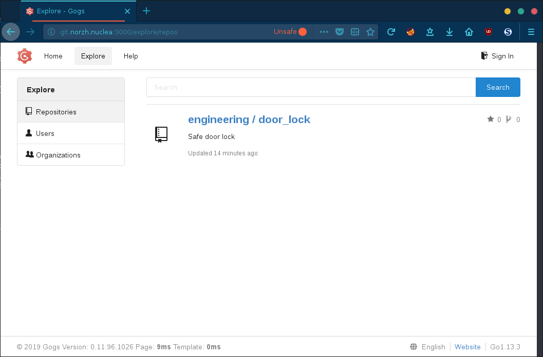
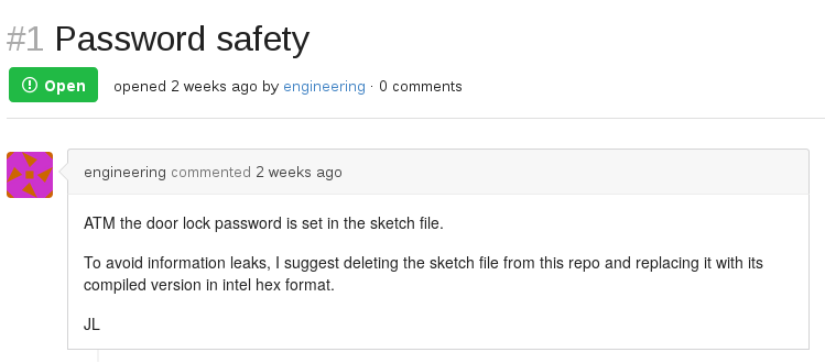
Looking at the issues, we’re informed that the project is based on a sketch file that has been removed and replaced by its compiled version:
Let’s now download the project files and inspect its commits:
git clone http://git.norzh.nuclea:3000/engineering/door_lock/
cd door_lock/
The commits log reveals that an Arduino sketch was previously indexed on the repo:
git log --name-status
commit d507311b0c6cd04482316e7bb754cbe33056b7c5
Author: Jean Luc <jl.engineering@norzh.nuclea>
Date:   Fri Nov 1 15:14:15 2019 +0100

    Add circuit + secretary testing build

A       circuit.png
A       door_lock/door_lock.ino.standard.hex
A       door_lock/door_lock.ino.with_bootloader.standard.hex

commit f364fec2328c74b3a3ddb7145345240ba25548c2
Author: Jean Luc <jl.engineering@norzh.nuclea>
Date:   Wed Oct 16 05:45:51 2019 +0200

    remove arduino sketch (prevent leaking password)

A       .gitignore
D       door_lock/door_lock.ino

commit ecd3d753dfb52fa526bb17dca5646e56ab5f6477
Author: Jean Luc <jl.engineering@norzh.nuclea>
Date:   Wed Oct 16 05:40:25 2019 +0200

    create arduino sketch

A       door_lock/door_lock.ino

commit ef3f305016365c9bfaa4418872ee5d4eb86f8ad0
Author: Jean Luc <jl.engineering@norzh.nuclea>
Date:   Wed Oct 16 02:40:24 2019 +0200

    Initial commit

A       README.md
Unfortunately, the sketch file has been removed immediately after its initialization and does not contain sensitive information about the locking system:
git show ecd3d:door_lock/door_lock.ino
void setup()
{
  // put your setup code here, to run once:
}

void loop()
{
  // put your main code here, to run repeatedly:
}
Focusing on the last commit, we get the compiled Arduino program encoded in Intel HEX format and a diagram of the circuit.
Let’s analyze these files!
Circuit analysis
The following diagram represents the entire circuitry of the door locking system:
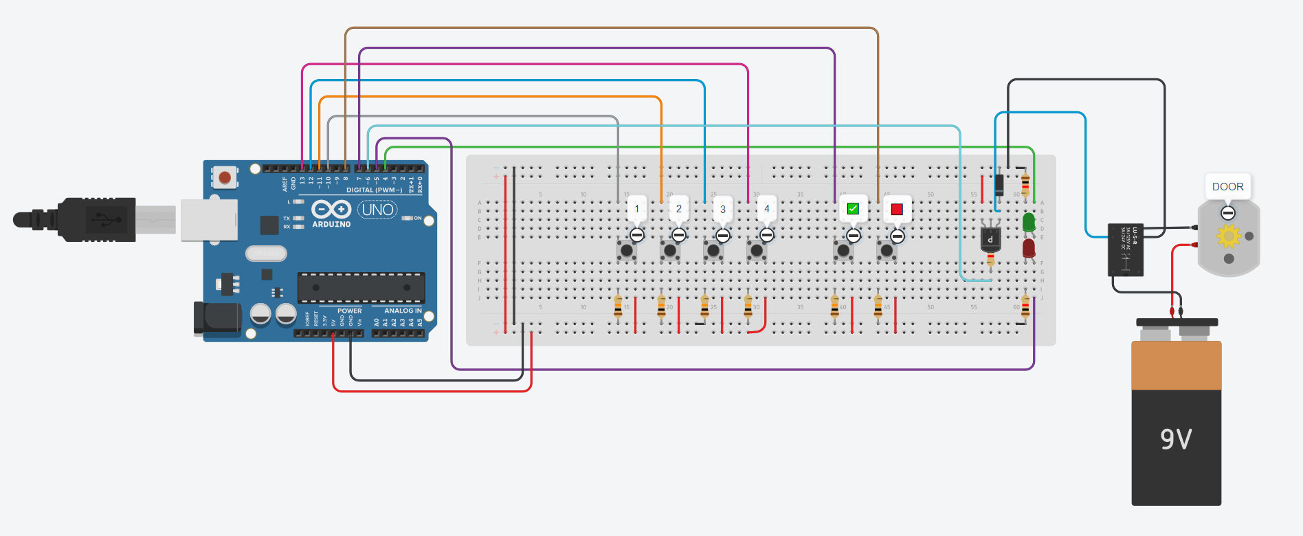
By zooming on each element and referring to various datasheets, we’re able to list the electronic components used in this circuit:
| Component | Description |
|---|---|
| Arduino Uno | AVR microcontroller |
| DC motor | Door locking mechanism |
| Power supply | DC motor power supply |
| SPDT 5V relay | Contol the DC motor see datasheet |
| Diode | Flywheel diode |
| PNP transistor | Control the relay, controlled by the Arduino pin #6 |
| Red LED | Controlled by the Arduino pin #5 |
| Green LED | Controlled by the Arduino pin #4 |
| Button 1 | Keypad 1 key, controlled by the Arduino pin #10 |
| Button 2 | Keypad 2 key, controlled by the Arduino pin #11 |
| Button 3 | Keypad 3 key, controlled by the Arduino pin #12 |
| Button 4 | Keypad 4 key, controlled by the Arduino pin #13 |
| OK button | Keypad OK key, controlled by the Arduino pin #7 |
| Cancel button | Keypad Cancel key, controlled by the Arduino pin #8 |
According to this circuit design, the Arduino program should be very simple:
- Turn off the PNP transistor on pin
#6(which turns off the DC motor) - As long as the
CancelorOKbutton has not been pressed:- Wait until a key on the keypad is pressed
- Save the key pressed
- If the
OKbutton has been pressed, check the PIN code - If the PIN code is correct, switch on the PNP transistor on pin
#6(which turns on the DC motor)
Let’s check it out!
Binary analysis
We’ve two files:
door_lock.ino.standard.hex: compiled chip program for Arduino ready to be stored in the microcontroller’s flash memorydoor_lock.ino.with_bootloader.standard.hex: the same file, but containing in addition the bootloader allowing us to flash the microcontroller
Let’s focus on the door_lock.ino.standard.hex file.
Before dropping the binary into IDA, we can decode the program using objcopy. It’s optionnal, but it allows us to analyze the binary before trying to reverse it:
mv door_lock.ino.standard.hex firmware.ino.hex
avr-objcopy -I ihex firmware.ino.hex -O binary firmware.bin
Okay, now we should have a valid program file, let’s check it using binwalk opcode scanner:
binwalk -A firmware.bin
DECIMAL       HEXADECIMAL     DESCRIPTION
--------------------------------------------------------------------------------
421           0x1A5           AVR8 instructions, function prologue
The Arduino board is an AVR powered microcontroller, so we can confirm that we work with a valid program. Let’s run IDA!
Reverse engineering
Processor selection
When launching IDA, we notice that the processor architecture is not detected, IDA can only know the actual processor type if the file format provides it.
Here, we know that our Arduino Uno board is based on the ATmega328 AVR microcontroller, so let’s select Atmel AVR.
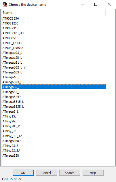
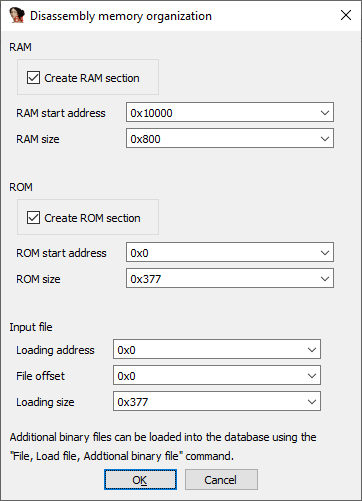
After pressing OK, the CPU selection dialog pops up and asks us to choose a CPU corresponding to the actual processor for which the program has been developped.
The problem here is that the ATmega328P is not in the list. As described in the Slot Machine writeup of the Google CTF, you can fix the .data segment if necessary (which is not worth it here), so let’s just select the ATmega32_L, create a RAM section and skip the EEPROM selection dialog box:
Actual reverse-engineering
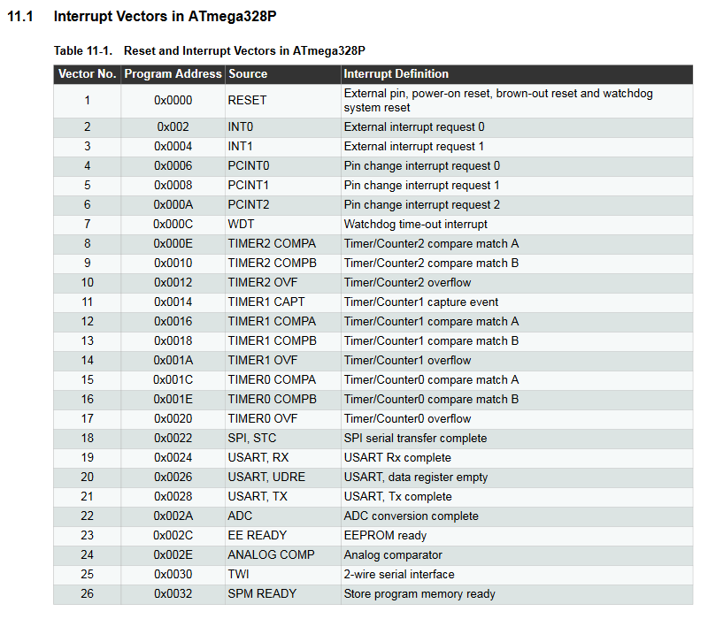
When the Arduino is powered up, it starts program execution from its very first memory address i.e. ROM:0000 which is by default defined as the reset and interrupt vectors:
Looking at the RESET vector, we get the address of the reset handler (ROM:0061):
ROM:0000                 j___RESET:
ROM:0000    940C 0061                  jmp     __RESET    ; External Pin, Power-on Reset, Brown-out Reset, Watchdog Reset, and JTAG AVR Reset
Let’s analyze it:
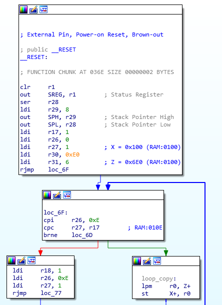
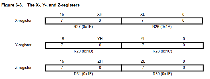
As shown in the illustration above, the reset function relies on registers R1, R17:R18, R28:R31, which are some of the 32 general purpose registers (R0:R31).
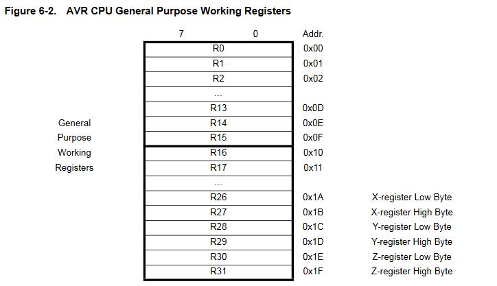
The last three register pairs are used as pointer registers for memory addressing, they are known as X (R27:R26), Y (R29:R28) and Z (R31:R30).
These Indirect Address Registers allow us to store 16-bit values, while standard registers can only contain 8-bit values:
The reset handler gives us interesting values such as the location of the data to be copied into SRAM:
X = 0x100: SRAM address from which the program variables will be writtenY: stack frameZ = 0x6E0: ROM address from which the data is copied0xE: the data length
We now know that the SRAM will be initialized with the content in the address range 0x6E0:0x6EE of the ROM. Let’s dump this content:
hexdump -s 0x6e0 -n 14 -x firmware.bin
Output:
00006e0    0002    0004    0002    0001    0003    0002    0004
00006ee
We can assume it’s the PIN code, but let’s check it out!
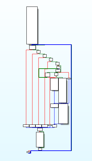
Main function
Based on the algorithm assumed above, we can expect to find a function with a large loop to read the PIN code on the keypad and a switch statement for the button functions:
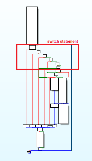
Looking closely at the function graph, we can identify a switch statement that should be the input test for the buttons:
By reversing some code blocks, we finally find the button reads:

And the code associated to each button:
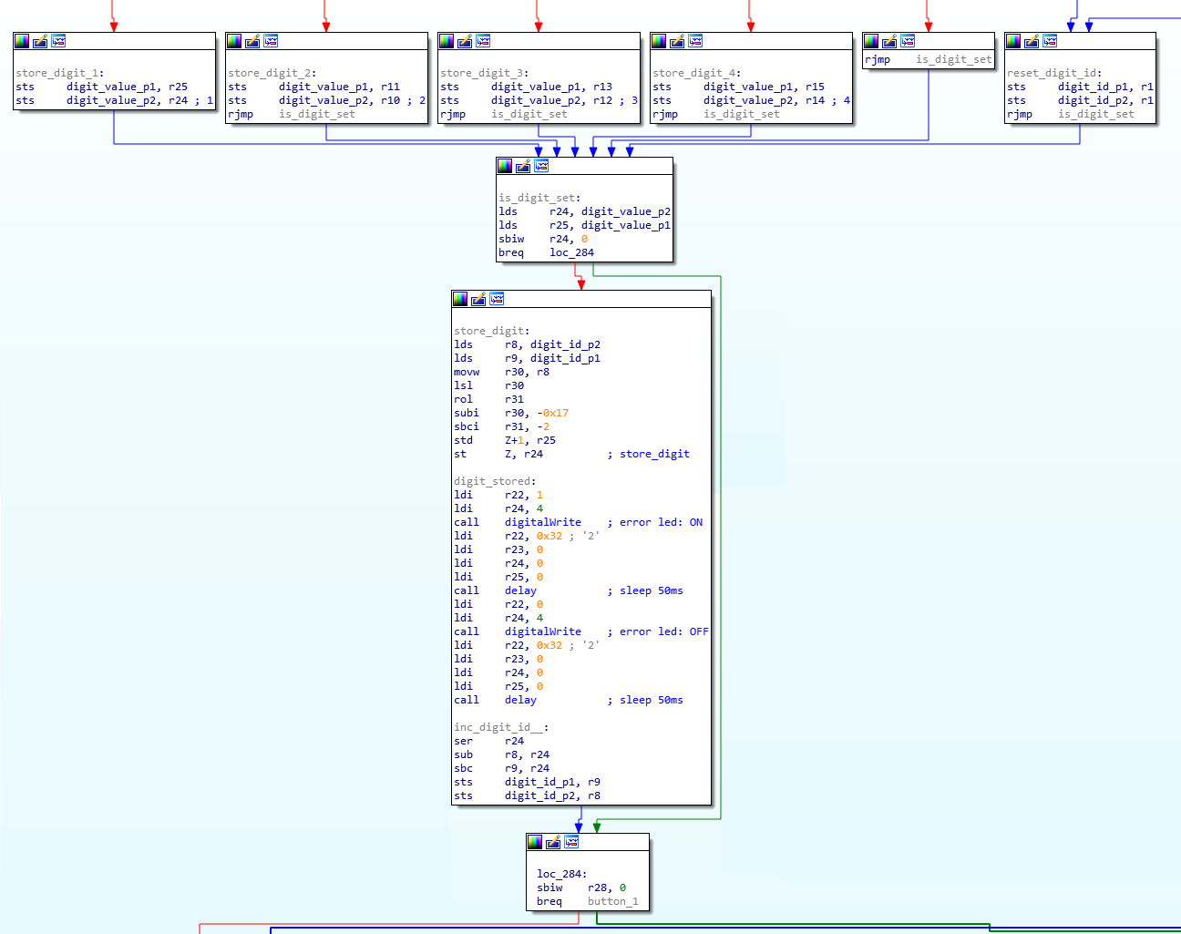
The above code simply stores the button ID using the Z register and increments the PIN code digit index.
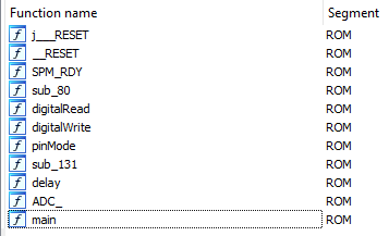
Further analysis allows us to get the program’s functions (most of them from the Arduino.h lib):
The last two buttons correspond to the Cancel and OK buttons.
The OK button should be associated with a function defined for PIN code validation:
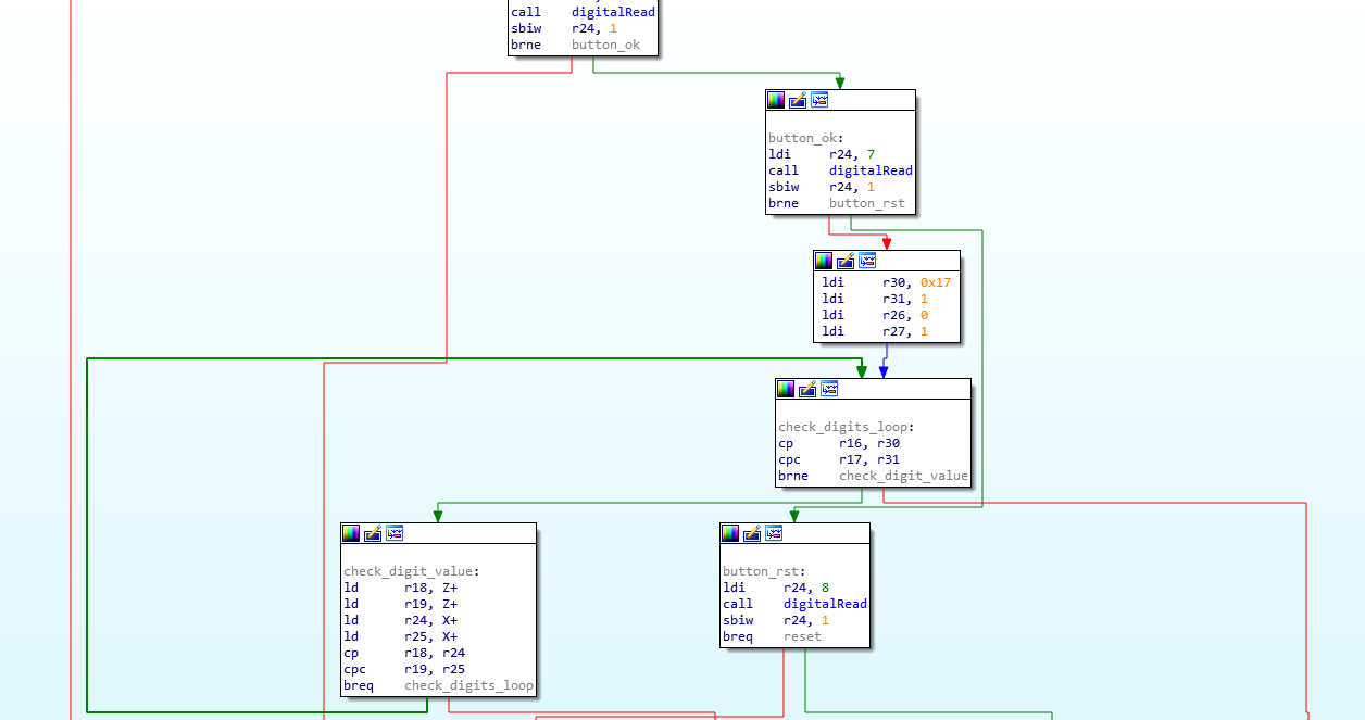
In the check_digit_value node, the registers X (R27:R26) and Z (R31:R30) are compared.
The Z register contains the user PIN code value and the X points to the SRAM section.
Therefore, the SRAM content is definitely the good PIN code!
FLAGS
Final flag is: ENSIBS{2421324}
Happy Hacking!